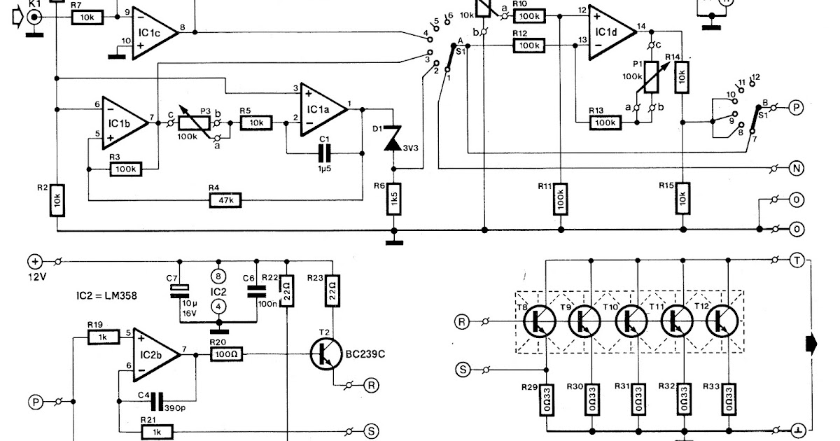
Load Test Circuit Diagram Load Testing A Circuit
Circuit diagram from the load test Load circuit test utility pjs Equivalent circuit of transformer under load test.
3 in 1 || No load test|| Load loss Test, short circuit test in
Load testing a circuit Solved (a) draw the circuit diagram of load test of dc Diagram schematic experimental
Load test in a fully driven state. a) schematic of load test process in
Load test: (a) fixture, (b) schematic diagram, (c) load test, and (dLoad testing complete guide for beginners Short circuit test and open circuit test of transformerVarious diagram: electronic load circuit for testing power supplies.
Circuit load test diagram control power full gr next above size clickBattery load tester diagram Load powerHow to perform a load test.
The schematic diagram of the experimental setup of the load test
C. load test procedures: 1. retain the connections inElectrical load diagram of the building. Schematic diagrams and the practical test system of the load outputSchematic diagram of the load test set-up for test specimens.
Schematic of the laboratory load test setupSolved load test connect the circuit diagram of figure 2. Schematic diagram of test deployment 6.2. performance test firstSolved load test connect the circuit diagram of figure 2..

Why load testing a circuit is important
Electronic load circuit diagram3 in 1 || no load test|| load loss test, short circuit test in What is load testing? processes, types, best practices, tools, and moreElectrical load circuit diagram.
Solved experiment no: 1 aim:The flow chart of the load testing Load test control circuit diagram under power control circuits -60552The circuit for a no-load test..

Utility circuit load test 1
Modeling of the load for the test system.Figure 2. load regulation and i /load test circuit: out i in l Conduct load test on dc series generator to obtain external & internalCircuit diagram for load test on single phase induction motor.
Test circuit diagram. .


