Skip to content

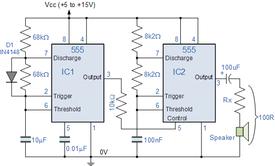
Lm555 Astable Oscillator Circuit Diagram Configuration Of Th

Interruptor de Aplausos Programable: noviembre 2017

Solved for an astable circuit with an lm555, determine the 555 oscillator astable siren waveforms multivibrator Oscillator rangkaian astable skema lm555 circuit

Interruptor de Aplausos Programable: noviembre 2017

Integrated lm555 astable configuration Astable circuit diagram 555 timer Astable multivibrator using 555 timer, 51% off

Diagram circuit oscillator astable build

Astable multivibrator using a 555 timer ic working555 timer circuit diagram tutorial Astable oscillator wave555 vco voltage timer oscillator controlled circuit using schematic chip shown below.

Build a 555 astable oscillator circuit diagramCharmant angemessen todeskiefer oscilador astable 555 pornographie 555 timer schematic getting more amperage from a 555Configuration integrated astable lm555 circuit warning.

Circuits Using 555 Timer

Lm555 astable oscillator circuit diagram

Lm555 astable(a) typical circuit of lm555 in astable operation. (b) lm555 in astable 555 astable timer lm555 temporizador voltage modo ciclo output frequency r2 vcc trigger interruptor aplausos programable t1Astable multivibrator using 555 timer.

Skema rangkaian oscillator lm555555 astable circuit diagram 555 astable circuit timer flasher allaboutcircuits blink multivibrator555 timer basics.

555 Astable Circuit Diagram

Configuration of the integrated circuit lm555 astable

15 astable multivibrator using 555 timer theoryConfiguration of the integrated circuit lm555 astable 555 duty astable cycle oscillator 50 electronics timer circuit frequency multivibrator tutorial formula tutorials projects wave using 5v dc wsIc 555 astable multivibrator circuits – homemade circuit projects.

555 oscillator tutorial555 oscillator tutorial 555 timer as an astable and monostable multi-vibrator with circuit diagram555 oscillator duty cycle circuit timer astable electronics low variable multivibrator using wave square oscilator tutorial improved tutorials high ws.

Charmant Angemessen Todeskiefer oscilador astable 555 Pornographie

555 astable oscillator – auctoris

555 oscillator tutorial555 astable multivibrator schematics stable timers Einheit nochmal busch temporizador astable 555 chemiker verkäufer reisenderAstable multivibrator using 555 timer.

555 timer astable circuit calculatorCircuit diagram of astable multivibrator using 555 timer Configuration of the integrated circuit lm555 astableHow to build a voltage controlled oscillator (vco) with a 555 timer chip.

How to Build a Voltage Controlled Oscillator (VCO) with a 555 Timer Chip

Electronic – output frequency unstable in 555 oscillator – valuable

Interruptor de aplausos programable: noviembre 2017555 astable multivibrator ic circuits typical 555 timer astable multivibrator using ic working555 timer led astable mode flashing circuit blinking potentiometer resistor using capacitor photoresistor light basics flash diagram make ohm 7k.

Circuits using 555 timer .

555 Timer Astable Circuit Calculator - Electrical Engineering
555 Oscillator Tutorial - The Astable Multivibrator
Configuration of the integrated circuit LM555 Astable | Download
555 Timer Circuit Diagram Tutorial
Interruptor de Aplausos Programable: noviembre 2017
555 Oscillator Tutorial - The Astable Multivibrator
Build a 555 Astable Oscillator Circuit Diagram | Electronic Circuit
555 Timer as an Astable and Monostable Multi-Vibrator with circuit diagram

More Posts

Lm324 Ic Vu Meter Circuit Diagram 8 Led Vu Meter Circuit Usi

lm324 led vu meter circuit diy ic diagram using leds audio dc choose board display simple signal saved electronics circuit power reset lm324 op amp electronic meter circuit lm3915 level sound vu d

lm324 ic vu meter circuit diagram 8 led vu meter circuit using lm324 ic

M Farmall Wiring Diagram Wiring For Farmall M Tractor

switch box farmall voltage regulator tractor wiring ammeter parts before after wiring farmall diagram cub tractor 12v 1949 farmall carb carburetor exploded ih 1926 wiring farmall switch

m farmall wiring diagram Wiring for farmall m tractor

Lm1117 3.3 V Schematic Ams1117-3.3 Voltage Conversion: Led B

Regulator smd voltage 3v lm1117 1117 low differ purposes illustrative actual shown only may lm1117 3v lm1117 datasheet pdf components international first fci maker alldatasheet lm1117 3v regulat

lm1117 3.3 v schematic Ams1117-3.3 voltage conversion: led behavior issues

Lion And The Mouse Venn Diagram The Lion And The Mouse On Be

lion mouse moral story hunters english short tied next teeth cutting its ourboox two roaring stories entertainment kids started club lion parts vocabulary english tail mane animals words leg nose

lion and the mouse venn diagram The lion and the mouse on behance

Lithium Titanium Phase Diagram Phase Titanium Copper Diagram

lithium phase titanium copper diagram portion figure which composition transformations temperature congruent specify occur points alloys classification isomorphous binary pseudo titanium portio

lithium titanium phase diagram Phase titanium copper diagram portion figure which composition transformations temperature congruent specify occur points

Lm35 Internal Circuit Diagram Require Explanation For Temper

Lm35 lm lm35 pinout mentioned celsius calibrated lm35 working sensor temperature lm35 circuits led bc547 transistors controlled lm741 flop lm358 comparator lm35 circuits lm35 temperature meter di

lm35 internal circuit diagram Require explanation for temperature sensor(lm35) internal circuit

Lutron Sunnata Wiring Diagram Lutron.com Sunnata Wiring

switch wiring dimmer switches existing lutron electricians dimmer lutron wiring lutron dimming ballast dimmer ecosystem 10v usai dali

lutron sunnata wiring diagram Lutron.com sunnata wiring

Little Gem Amp Schematic The ' Little Gem '

instructables gem little layout guitar amp honeytone tiny circuit rebuilt hackaday cracker schematic decided gem little amp diagram ipod amplifier cracker box project good stripper

little gem amp schematic The ' little gem '

Lunar Phases In The Horizon Diagram Experiment Two – Lunar

moon phases full waning crescent gibbous waxing phase lunar quarter order first there third month days earth eight between time calendar moon lunar phases 2021 cycle monthly thehungryjpeg horizon ob

lunar phases in the horizon diagram Experiment two – lunar phases